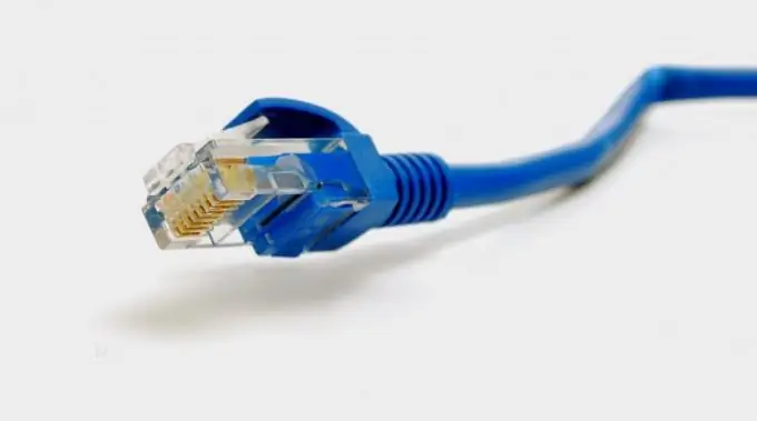
A patch cord is an Ethernet cable that is equipped with RJ-45 plugs on both sides. It is designed to connect a computer to a switch, router or other similar device.

Instructions
Step 1
If the patch cord has not yet been manufactured, it must be manufactured. Cut the UTP cable containing four twisted pairs to the required length. Connect an RJ-45 plug on each side. To get a patch cord, connect either both connectors according to scheme A, or both according to scheme B. With this cable, you can connect a computer to a switch or router. If one plug is squeezed according to scheme A, and the other according to scheme B, you will get not a patch cord, but a crossover - a cable for connecting either two computers, or two switches, routers, etc.
Step 2
To connect the plug according to any of the schemes, turn it with the contacts up and away from you. For scheme A, connect the wires in the following order: white-green, green, white-orange, blue, white-blue, orange, white-brown, brown. For diagram B, change the connection order to this: white-orange, orange, white-green, blue, white-blue, green, white-brown, brown.
Step 3
After inserting the conductors into the connector, clamp the latter in a specially designed tool (crimp). Do not use surrogates for this, such as pliers and ordinary screwdrivers.
Step 4
Rotate the plug so that the bulge on one of its sides coincides with the recess on the network card connector of your computer, switch or router. Insert it until it clicks. To remove the plug, push the tab towards the body and gently pull on the cable. A sign of normal operation of the equipment is a constant glow of the green LED, accompanied by a blinking yellow LED when data is being transmitted. On some devices, LED colors and display algorithms may be different.
Step 5
For network equipment, usually one of the connectors is allocated as input (Uplink), and the rest are output. Input and output, they are named conditionally, since all connectors are designed for both receiving and transmitting data, but the Uplink connector is connected to an upstream switch or router. If the circuits of the device connected to this connector are out of order, on some devices it is possible to use other free sockets as input (with the Auto-Uplink function). Any equipment must not be locked to itself, otherwise collisions will arise that interfere with data transmission.


