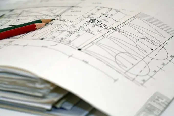
A CAD drawing looks cleaner than a hand-drawn one. CAD allows you to set the thickness and type of drawn lines, make complex cuts, mirror images of objects, paint with color and hatch.

Instructions
Step 1
Open CAD AutoCAD on your personal computer. To do this, double-click the left mouse button on the AutoCAD icon located on the desktop, or select this program from the list of programs in the Start menu.
Step 2
Load the drawing in which you want to hatch. To do this, in the main menu of the program, click "File", then "Open" and select the drawing file you need. If you are using the English-language version of the program, click the File and Open commands, respectively.
Step 3
Open the "Draw" submenu and select the "Hatch" item in the drop-down list. You will see a window for editing the shaded areas of the drawing. In the Pattern field, set the standard 45 ° thin hatch, which will be the ANSI31 pattern in the program. In the "Structure" field, you can choose other hatch options. Enter the desired hatch angle in the Angle field. The default angle is 0 °. In the "Scale" field, select the scale of the hatch, correlating it with the dimensions of the shaded area.
Step 4
Select the area you want to shade. To do this, in the editing window, select the item "Add: selection points" and click with the mouse inside the area that is limited by the outline of the drawing lines. Then press Enter and in the hatch edit window press OK. Please note that the entire contour must fall within the visible area of the drawing, that is, fit into the AutoCAD window that is open on your computer, otherwise the program may generate an error. In addition, the loop must be closed. To do this, when making a drawing, be sure to use snaps and carefully monitor the intersection of lines of all types, especially polylines, circles and arcs.
Step 5
Pay attention to the thickness of the lines with which the hatching is performed. They should be thinner than the main lines of the visible contour with which the part or assembly unit is drawn. You can set the line thickness in the "Layers" submenu. Also set the color of the dashed lines so that you can distinguish them from the main lines in the drawing.


