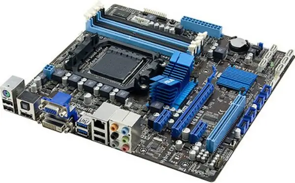
The motherboard is precisely the microcircuit that allows all parts of the computer to perform certain tasks together. When assembling a PC from scratch, you need to install it correctly.

Instructions
Step 1
The processor must be installed in a suitable socket called a socket. It is important not to bend the stone "legs", if any, and install it according to the marking, otherwise the part may simply burn out when the PC is turned on. Difficulties can arise when installing a processor fan. In a number of situations, before fixing the motherboard to the case, part of the stand for the cooler is screwed onto its back side. Please refer to their technical documentation for successful processor installation and ventilation. Connect the cooler wiring to the motherboard connector labeled CPU_FAN.
Step 2
A cover for connectors on the back of the motherboard is usually included in the kit. It must be slipped onto this panel so that the connectors protrude out before connecting the chassis to the system board. The motherboard has small bolt holes. In those places where the holes of the board for fastening coincide with the same holes in the case, you need to put special legs that come with the microcircuit. Then the motherboard must be screwed to the rack so that the legs are between it and the case. Plug the chassis fans into the SYS_FAN connectors.
Step 3
The RAM should be inserted into the corresponding connectors on the motherboard. They are easy to recognize by their appearance, and they are signed DIMM_DDR. The video card is inserted into a PCI Express slot. Sometimes the video card has a small ribbon cable to connect to the motherboard. Sound and network cards, if any, are connected to the PCI slot.
Step 4
The power supply is connected to the motherboard via the ATX POWER connector, which has 24 or 20 connectors. Sometimes with the main loop there are 1-2 additional ones for 6 or 4 contacts. Winchesters and DVD / CD drives are connected to the motherboard's SATA and power supply molex connectors.
Step 5
The end will be the connection of the front panel of the case. From it there are thin wires, signed by 2-3 letters. They need to be connected to the contacts on the motherboard that have the same letter code. POWER SW and RESET SW will allow you to control rebooting and turning on the PC, wires with the inscription LED turn on the lights on the case. SPEAKER, RETURN, SPKOUT and MIC are the wires from the audio and microphone jack. It remains to put the lid on the case. Now you can connect peripherals to the back panel, connect the power cable and turn on the PC.


