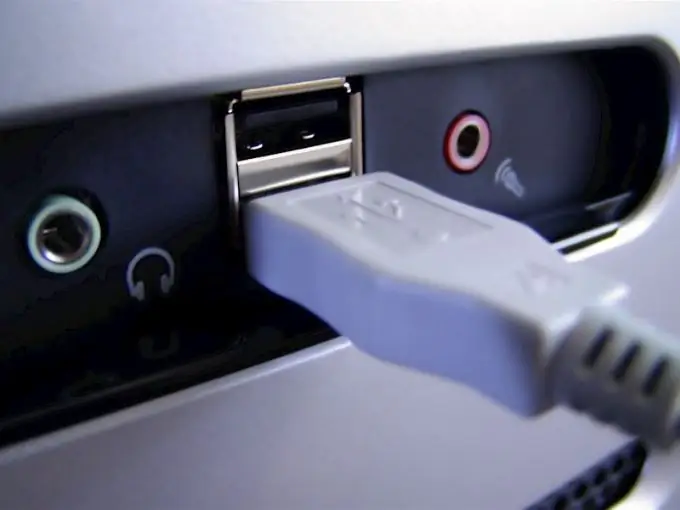
The presence of USB ports on the front panel of the system unit is a very convenient solution. Usually these ports are connected, but in some cases - for example, when assembling a new computer from components - you have to connect these ports yourself.

Instructions
Step 1
Disconnect your computer from the network. Press the power button, this will discharge the charge on the capacitors of the power supply. You can now connect the front USB ports.
Step 2
Remove the left side panel of the computer (the computer is facing you). On the motherboard, look for small yellow or blue connectors, usually at the bottom.
Step 3
Each such connector has two rows of pins (needles): in one row there are five, in the other four. Let's call the left or right side of the connector, where both pins are located, side "A". The second, with one pin - "B".
Step 4
The five pins, starting from the "A" side, are labeled as follows (in series): VCC1 + 5V, Data -, Data +, Ground 1, NC.
The last pin - NC - is not used.
Step 5
The four pins of the second row, starting from the "A" side, have the following markings (in series): VCC2 + 5V, Data -, Data +, Ground 2. There is no fifth pin (pin) in this row.
Step 6
Examine the connector on the end of the ribbon cable coming from the USB port. It should be labeled: VCC1, Data 1 -, Data 1 +, Gnd 1. The labels may be slightly different, but it's easy to figure it out - on the first socket under the pin, VCC or +5 V is always indicated, the last is Ground or GND.
Step 7
In most cases, connector wires are in standard colors:
+ 5V red
Data - white
Data + green
GND black
Step 8
Connect the connector from the USB cable to the socket on the motherboard to the row of five pins. The first - on the "A" side - must be connected to VCC1 +5 V. The fourth - Gnd 1. The last fifth pin remains free. There is no pin next to it in the second row.
Step 9
To simplify the connection, special adapters can be used to exclude the possibility of incorrect connection. They are suitable for connectors on the board, usually blue, with a small side and a key and allowing you to connect the adapter in only one way.
Step 10
The pins on such an adapter are designated as + 5V, P2-, P2 +, GND. If you have such an adapter (they can be supplied with the motherboard), connect the ribbon cable connector to it in accordance with the marking, then insert the adapter into the socket on the motherboard.
Step 11
With all USB ports connected, close the side cover. If you are still not completely sure of the correct connection, then after turning on the computer, connect a USB mouse to the front port. If the mouse works fine, then everything is connected correctly and you can safely connect flash drives and other equipment.


